Sunday, February 28, 2016

Lego Racer

The third project of the class was building a car out of Legos that could hold a 1 kg weight and go as fast as possible on a 4 meter course using an old gray motor that had no interior gearing. My partner, Magnolia, and I decided to start with putting together different gear trains to see which ones seemed to provide torque for the motor but also kept the speed. 

Here are some of our first iterations of our gear trains:
24:40 | 8:40 | 40:24 | 8:40
1:25
8:24 | 8:40 | 40:24
1:9
8:40 | 8:40 | 8:40 | 40:24
1:75

Once we had a few options, we decided to use the two big wheels as the driven wheels since they would pull the car a further distance per rotation. We also decided since the two driving wheels would be the ones driving, we only need one wheel at the back to make the car level and rotate along with the driving wheels. We decided to use the mid-sized wheels since it held the gear train more to the level of the big wheels. 

We decided to build up from our 1:75 gear ratio train since it seemed to provide enough torque that it would be able to carry the weight and still move. Since the weight we got did not have a flat bottom or top, we thought that we should build a structure that would hold it. Magnolia got to work on that as I figured out where to attach the wheels, PicoCricket, and motor. We decided that having the motor in the inside would make the weight of the car more even rather than have the motor on the side. We then thought that the PicoCricket should just be on top of the motor as well since it would keep all the weight in the center. The actual 1 kg weight and its structure was also then put right next to the PicoCricket to keep all the weight together. 

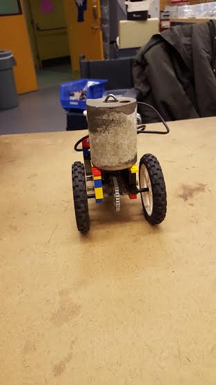
Magnolia's awesome structure that did not allow the weight from rolling around. It was really sturdy and if you held it upside down, the weight would not fall out of the structure. 
Our tank from the front

the tank from the back
Our first iteration that was able to carry the weight and move was a mammoth of a car hence the name the tank. It had a 1:75 gear ratio which at that time we thought was pretty good. We were pretty ecstatic when we turned it on and it was able to move with the weight but it was so slow! It took a little over 40 seconds for it to go across the 4 meter course. 

Amy let us know that we should experiment with gear trains with less gears and to make sure that everything was perpendicular which was something that we had not really kept in mind as we made the first few iterations. She also suggested to try different gear trains and record how fast they were.

Magnolia and I decided we needed a much smaller ratio so we first played around with the current 1:75 gear train we had. We removed the last 40s which made the gears 8:40, 8:40, and then 8:24 which we calculated to be the same as the one we currently had but at least had fewer gears. We created more gear trains with much smaller ratios. 

8:40 | 40:24 | 8:40
1:15

8:24 | 8:24 | 8:24
1:9
With just the motor attached to the gear trains, we thought that they would be great since they seemed to be going so fast but once we attached the weight to it, the car would not even start. For the 1:9 car the car would not start at all, but the 1:15 car would start and move for a second and then stop.

Xi Xi suggested that we make our car much thinner and less bulky. She helped us realize that having a wide car made the wheels much further which then placed more weight on the axles which created more friction. Xi Xi also let us know that our weight should be able to just sit on the car without the additional stabilization from a structure holding it. 

In order to make our car much smaller, we decided to try putting some of the gears together vertically and have the initial 8-tooth gear right on the axle jutting out from the motor and then place the motor slightly above the 40-tooth gear attached to the 8-tooth gear. We decided to place the motor slightly above because in order to have the 8-tooth gear attached to the motor, and then have a 40-tooth gear attach to the 8-tooth, another 8-tooth gear had to go in the middle because the motor would touch the 40-tooth gear. So by having the motor slightly above the 40-tooth gear, the 8-tooth and the 40-tooth gears were able to be attached with out any additional gears. The rest of the gears in the train were attached on the same level. By having the motor higher up, we were also able to make the car much thinner. We then just attached a long thin Lego across the car for the weight to lean against and it was enough to keep the weight from falling off. 

Final iteration
8:40 | 40:24 | 8:40
1:15
top view
side view
back view

We found that if any Lego was attached across from one side of the car to the other on top of the motor, the gears would not turn. We realized that this was because having any force pushing down on the motor would cause the 8-tooth gear attached to it to push down on the 40-tooth gear causing them to not move. So we then decided to have the weight closer to the back of the car so that it would not exert a downward force on the motor and the PicoCricket was attached to the front of the motor for the same reason. Our final iteration was able to cross the course in about 11 - 12 seconds. During race day, it finished the course in a little over 12 seconds. 


Reflection:
Given more time, I would try to change the gear train to have less gears since it would decrease the amount of friction. I would also try to cut down on the number of Lego pieces used and also try to make the car much smaller. Having a much smaller car, I think would make it much faster. I would also love to try to figure out a different way to attach the motor. I think the main reason why our car was not as fast as the other 1:15 cars was because of the way out motor was attached. I believe how we currently have it does not allow the motor to turn its axle freely which caused the gears to turn slower. 

Engineering Analysis:

Our final gear ratio was 1:15 (8/40 * 40/24 * 8/40). We decided this gear ratio by trying different ratios out and finding which one was right in the middle and gave us the perfect amount of torque and speed since finding this sweet spot would give us the most amount of power. When we made the different iterations of gear trains, we found that the 1:75 (8/40 * 8/40 * 8/40 * 40/24) we initially tried provided so much torque that it was way too slow at 40 seconds. We also tried a ratio that was 1:25 (24/40 * 8/40 * 40/24 * 8/40) and that was at around 20 seconds which was much faster so we decided that we needed to lower our ratio even more. We found that a 1:9 (8/24 * 8/24 * 8/24) was very fast but it would not move with the weight. The 1:15 (8/40 * 40/24 * 8/40) was not as fast but it at least moved with the weight.  

Monday, February 22, 2016

Well Windlass

The second project of the class was to create a well windlass that would span a 12 cm gap between two tables and be able to lift a filled 1 liter bottle 10 cm above the gap in less than 45 seconds, and if possible under 30 seconds. We were limited to using 50 cm of Delrin rod and 500 square cm of 3/16" Delrin sheets. My partner for this project was Nanaki.

example of a well windlass
We started brainstorming ideas of how we wanted our windlass to be. We knew we needed to make the round part of the windlass which the string would wound around, a crank to turn the round part, and a base to hold it. 


During brainstorming, I focused on how to make the string wound around more of the round part so that it could pull up the bottle faster. I thought that perhaps cutting the rod into four 10 cm rods and one 2.5 cm rod and 7.5 cm rod and then attaching the four rods onto two round pieces of delrin sheet would create a larger area for the string to wrap around instead of just having it wrap around one rod. The 2.5 cm rod would then be attached to one side of the round part and the 7.5 cm rod on the other side. The rods and sheets would be attached through the hole and peg mechanism where the rod would be the peg and the holes would be in the sheets. 

We then had to figure out what would hold the round part of the windlass. We decided to have two rectangular sheets standing on each side of the 12 cm gap with a slot on the top for the round part of the windlass to rest on. These rectangles would then be attached to a square sheet and then a thin rectangular part would stand on an angle to connect the square part laying down and the rectangular part standing up. We also decided to have a smaller rectangular part attach to the square part to kind of hug the table. We thought of attaching the base parts by heat staking them since we wanted our base to be pretty strong and not to pop off of holes.

We also thought of using gears in order to have the crank turn the round part faster. We saw a video on YouTube which made us think of building the round part as two tubes of different diameters so that the bigger tube rotates in one direction while the smaller one goes the opposite way. This would allow the bottle to be steadily pulled up. 

We made a cardboard prototype of our first idea and reserved our gears and alternating tubes ideas to be thought of more for the next day. 

We decided that it would very complicated to learn how to draw gears on SolidWorks and we could not figure out how to make the alternating tubes idea and so we just stuck with our first idea.. So we then calculated an approximate area of our windlass and it was well over 500 square cm and so we decided to decrease the area of our windlass by creating triangular cutouts on the base parts. 
As Amy went around seeing how our designs were coming along, she let us know that we would encounter the problem of the weight of the bottle pulling the two base parts inwards towards the gap and so we would need something to push back the base parts. So we then decided to add two beams that would span the gap and be attached to top portions of the two standing rectangular parts. Because the round part was much taller than the base, we needed to add 5 more cm to the top so that we could attach the beams and the round part could still turn.

We began creating our SolidWorks drawings and by the end of the day we had drawings of two of our base parts: the square lying down with holes and pegs, and the rectangular hugging the table with holes on one side. 

We then printed out practice holes and pegs to make sure that they would fit tight enough. We made the pegs 3/16" by 3/16" +0.3 mm since the sheet was 3/16" thick. We added the 0.3 mm to account for the laser cutter cutting more than what the drawing states. The holes were 3/16" by 3/16". Although we initially thought of heat staking the holes and pegs together, we found that our holes and pegs were a very good tight fit. The holes for the Delrin rod were best tightness at 6.25 mm. 

We printed one side of our base and we found that we cut out too much. The base seemed too thin and not stable enough to hold standing rectangle and the round part. 

We also wanted to change how we turned the round part. Initially we thought of turning it from the middle of the round part but it would be more effective to have the crank on one side of the circle so that per turn we did the round part would turn the same amount.
So we decided to rethink our design to incorporate a larger, stronger base that could possibly hold our new-ish round part. We came up with triangular bases with one side being an A that would have a hole near the top where one side of the round part would attach to and the other triangular base would be half a triangle with one side of the round part sitting on it. Another curved part would attach to the half triangle to hug the round part of the windlass and hopefully hold it enough. Two beams would go across and attach the two triangles and keep them from being pulled inward by the weight of the bottle. 

When we printed out our design though we found that the half triangle did not keep the round part steady at all as it turned. We thought of perhaps extended the half triangle so that it would hug half of the round part but we decided to print out another one of the A triangle to attach the round part both in the middle. By doing this though, we would be able to directly turn the round part like we planned. We solved this problem by attaching another round part on the outside of the triangle with a rod attached to it. We could then turn this wheel in order to turn the round part of the windlass. 
When we printed out the parts and put it all together, we found that the structure could hold the weight of the bottle but it was not able to turn and pull it up because the holes for the rods were not tight enough and so every time we tried to turn the wheel, only the rods would rotate around their holes and not rotate the whole round part. Other people were having this problem and they told me that I had to connect the rods to the circles using piano wire. A bushing would be attached to the circles perpendicularly using piano wire and then piano wire would be used again parallel to the circles and through the rod. This only had to be done to the side of the crank but it had to be done to the crank it self as well as the circle part it was attached to. But after all that work, we finally had a working windlass! The only thing we had left to change was to make a slightly larger rectangular base since our base was a bit small and if the windlass slid around, it would just fall into the gap.
Engineering Analysis:
We tried solving the problem of beam bending by having shorter rods to hold the water bottle and there were more of them a little bit spaced apart so the downward force of the bottle would not only be exerted on one rod at a time but two at a time. The structure was pretty sturdy due to the triangular standing parts being thicker and they were attached to larger rectangular bases. We tackled the time specification by first having a round part that would wind up more of the string per turn but also by making the crank easy to turn. Having a wheel like crank made it much easier to turn the whole round part which allowed us to bring up the bottle in less than 30 seconds. 

Reflection and the future:
It would have been really nice to figure out our first few designs would not be stable enough or would not work at all much earlier in the process. It's a lesson to us to next time try to create our drawings and prototypes much sooner so that we have more time to address their problems and create solutions. 
If we had a bit more time, I would love to add a part that hugs the table so that I would not need to hold down one side of the windlass as I turned it. I would also try to thin out the base in order to use less material. I would also like to try using the square/rectangular beams for the round part that the string would wind around. Another team did that and I thought it was amazing. It was such a great idea so I would really love to see how it would help my design. It would most likely remove my need to piano wire the circle parts and the rods together which would be really great since the piano wires kind of stick out a bit and could possibly be a hazard. 
Accounting:
Triangle Base Part (A): 102.31 sq cm each * 2 = 204.62 sq cm
Rectangular Base Part: 20.08 sq cm each * 2 = 140.16 sq cm
Circle Part/ Wheel: 45.67 sq cm each * 3 = 137.01 sq cm
Bushings: 2.84 sq cm each * 8 = 22.72 sq cm
TOTAL: 504.51 sq cm

All 50 cm of Delrin rod was used.

The four bushings in the round part are not really necessary so if we removed them, our area would instead be 493.15 sq cm. We added them to the structure at the very end to hopefully keep the string in the middle of the round part. 

Monday, February 15, 2016

Mechanisms

http://kmoddl.library.cornell.edu/model.php?m=467

This mechanism first caught my eye because when I first played the video I thought it could be used as a way to pull up a bucket of water or an elevator. But as I read the way it worked, I realized that this mechanism actually is limited to a certain range of linear motion but it delivers a much more powerful force downwards every time the piston rod goes down. This is due to the transfer of high speed turns of the larger wheel to the slower turns of the large gears. The strong force created by the straight line drive used to be used for steam engines but I think it could also be used for machines that crush objects.

http://kmoddl.library.cornell.edu/model.php?m=451
Special mention: I thought that this out of line drive was so cool since it only works when the two shafts are at the same angle but I did not really understand how the two tubes were able to rotate each other. 


This is a straight line drive which transforms a rotational motion into linear motion. The rotating motion is created by a large wheel with a small gear in its center, a larger gear sits on top of the smaller gear and another larger gear is right next to the larger gear on top of the small gear. The large wheel is turned which then causes the small gear to rotate which then makes the larger gear on top of it to turn and then the larger gear besides it turns as well. This turning motion is converted into linear motion by two cranks, each attached to one of the larger gears on one end and the other attached to one beam which is attached to the piston rod, that turn with the larger gears causing the piston rod to move up and down.

Sunday, February 7, 2016

Bottle Opener Part II.

Day 3

Professor Banzaert helped us make one part from the two parts of the handle and curved part that we made before and so we were finally able to create out bottle opener using the laser cutter!

SolidWorks drawing of our first prototype of the bottle opener

Laser cutter in action!

First Prototype
Our first prototype was a failure. The curved portion was way too large and could not hug the bottle cap at all to put any pressure down on it nor force up to remove the cap. We decided to make the curved part to be much smaller so that it could better hug the bottle cap. We also decided to make the thin part meant to be tucked underneath the cap to be a little thicker so that it would be less likely to break. We also decided to make the longer portion thicker as well.

Drawing of Prototype #2

Prototype #2

Our second prototype was also a failure. We thought we had the correct measurements. The space between the bottle cap and the curved portion should have been less than 1 mm but it was actually about 1.5 mm. We found that since we were using the thickest Delrin, the laser cutter had to go through the sheet three times. This would have caused the discrepancy between the SolidWorks measurements we had and the actual ones. This actually caused the thin nib part to be so thin that it broke the first time we tried to use it. Since this was a failure we decided to make a few more adjustments. We added 1.5 mm to top part, the curved part, and the nib part. We also added a little circle on the other side so that we could perhaps hang it on a  hook afterwards. 

Final drawing of bottle opener
Final bottle opener
And third time's the charm! It finally worked! My partner and I were elated! We couldn't believe it finally worked.We tried twice more just to make sure it wasn't simply luck and it still worked! The nib part got a little chipped after the first use but it was still able to open the bottle.

The goal of this first project was to create a bottle opener. We wanted to create a bottle opener that would be easy to use and would hopefully be able to withstand constant use. We used the idea of cantilevers to create our design. 
example of a cantilever
In a cantilever, the deflection, δ, is the amount of bending a beam withstands. It can be calculated using this equation:


F stands for the force applied on the cantilever/ bottle opener. L represents the length between the hand holding the bottle opener and the tip where the force is being applied. E is for Young's Modulus which is a constant property of the material. I represents the moment of inertia which can be calculated using this equation:


In order to minimize the deflection, we had to increase the moment of inertia as well as minimize the length. We did not want to have the length of the bottle opener too short because it would have made it too difficult to hold and twist up against the bottle cap. So we then focused on trying to increase the moment of inertia by making the nib part that went underneath the cap thicker by choosing the thickest sheet of Delrin which increased the base and a little longer which increased the height of the moment of inertia. The moment of inertia was increased just enough that our bottle opener was able to successfully open a bottle.


Evolution of our bottle opener
If we were given more time, we would have tried to make the design more aesthetically pleasing or interesting. We would have also tried to make it more pocket friendly so that one could attach it to their key chain. We would also improve on the nib part. It's still way too thin and will most likely break after a few more uses. If we had more time, we could have experimented a little more on trying different widths and heights for it as well as maybe using a different material for it, maybe a metal. But overall I'm proud of our bottle opener. I think that it's a nice little simple thing to look at and use and for now it at least still opens bottles.

Fastening & Attaching

This past Tuesday, we learned different ways of how to connect Delrin as well as how there are different fits of bushings on a Delrin rod and of slots and pegs. The classroom was divided into three different stations: the thermal press/ heat stake, the drill press, arbor press, and piano wire, and Calipers.

At the thermal press/ heat stake station, we learned how to melt two pieces of Delrin together to create one piece. This would be a very good technique for permanently connecting two pieces together and creating a stable part. It would be great at making the base of something that we would not want to move very much. It would not be very good for creating a movable and flexible part. It also causes one piece of Delrin to have round nub on it.

At the drill press, arbor press, and piano wire station, we learned how to connect two pieces of Delrin together by drilling holes in them and connecting them with piano wire. The benefits of this technique are that it is not permanent and so the pieces could be disassembled, it seems to be sturdy, and the pieces are movable and flexible yet still stay connected. Another great thing about this technique is that we can choose how tight or loose we want the holes to be and so we can decided if we want the delrin piece to be able to move all the way around the piano wire or if we want it to be held tight and steady by it. This technique would be great if we were making a bridge. The drawbacks of this technique is that there would be permanent holes in the Delrin and so placements of the holes must be well thought out and done correctly and it is also not permanent.

At the calipers station, we learned about how to connect pieces by designing them to be pegs and slots. We would design one piece to have the peg part that juts out on one of the sides while the other piece has the slot where the peg would go into. This technique would be good for creating designs that we would want to be able to easily disassemble like a fold-able table. This is also great because we can choose how tight or loose we want the pegs and slots to be. A tighter fit between the pegs and slots would create a sturdy design. A few drawbacks of this technique are that two parts would not be very movable and flexible and it is not permanent.

At the calipers station we also learned how to use calipers in order to measure bushings, rods, and sheets of Delrin.

Here are the measurements of the different types of bushings as well as the rod. There seemed to be at least a 0.02 mm difference between bushings of the same fit. The rods' measurements seemed to be the same though.

Bushing Fit Type
1st measurement
2nd measurement
Loose
6.58 mm
6.60 mm
Snug
6.37 mm
6.39 mm
Press/ tight
6.22 mm
6.28 mm

Delrin Rod Measurements
6.35 mm
6.35 mm

A press/tight fit bushing had an inner diameter much smaller than the rod's diameter. The press fit bushings' diameters fell in between 6.22 mm and 6.28 mm which seems to be a fairly large range but they are still smaller than the actual diameter of the rod which explains why it is difficult to place a press fit bushing around a rod. Tight bushings are most likely used to connect pieces that you would not want to move a lot or barely at all. It would be used to keep a section steady.

Meanwhile, a loose fit bushing has a much larger inner diameter than the rod. There was around a 0.25 mm difference between the diameter of the rod and the bushing explaining how easy it was to place the loose bushing around the rod and move it about. A loose bushing would most likely be used to connect pieces that one would want to still be able to move and bend.

Next we measured the slots made from Delrin.


Actual
measurement
SolidWorks measurement
Discrepancy between measurements
Line 1
0.141 in
0.135 in
0.06 in
Line 2
0.133 in
0.125 in
0.08 in
Line 3
0.125 in
0.115 in
0.10 in

The actual measurements were larger than the SolidWorks measurements. This could be due to the laser cutter cutting through the Delrin unevenly. We learned that the upper portion of the plastic would be melted down more than the lower part since the laser goes through top part more than it does the lower parts especially if the plastic must be cut more than once. Since we had the caliper tips touch the bottom of the slot when we measured the slots, it measured the lower and thicker portion of the slot. We should have also measured the top portion of the slot to see if it had closer measurements to the ones stated by SolidWorks. Since the laser cutter cuts the plastic at a slight angle and usually more than the stated measurement, when deciding measurements for designs, we should add at least a 0.05 in or 2 mm buffer region for the laser cutter.

We then measured tight fitting slot and peg.The slot was 7.04 mm by 5.10 mm while the peg was 6.89 mm by 4.92 mm. The longer side of the slot and peg had a difference of 0.15 mm and the shorter side had a difference of 0.18 mm. So we found that most likely in order to create a tight fitting slot and peg, there must be around 0.15 mm difference in width and length between the peg and slot.


Monday, February 1, 2016

Bottle Opener Part I.

DAY 1

Our first task of the semester was to get in touch with a skill that we may have buried deep within us: creativity. I know for me that skill is rusty. We learned that by practicing brainstorming, we can hone in our creativity. We first brainstormed different ways to solve the problem of having to walk through snow-laden sidewalks as well as for wheelchairs to go through such paths.

We were then presented with the our first project of the semester: creating a bottle opener. The first thing my partner, Sara, and I did was brainstorm for a few min. We were able to come up with about 8 designs.

Sara's designs on the left and mine on the right

We debated between choosing the hook-like bottle opener type or the type with a rectangular or circular opening in the middle for the bottle cap to go in. We ultimately decided to create the hook-like bottle opener and came up with this design:
Final bottle opener design 


We then created our foam core model and we found that cutting curves in the foam core was more difficult than we anticipated. But after a few minutes of struggling between making sure we were cutting through the foam core and attempting to make the curves smooth, we made a very rough but nice little palm sized bottle opener.
Foam core model
DAY 2

Using the foam core model as reference, we started drawing our design in SolidWorks. This was another task that proved to be more difficult than we thought. We first tried to draw one rectangular part and cut out the curved parts of the bottle opener but that did not work out too well. We then decided to draw the bottle opener in different parts and after approximately two hours we succeeded in drawing the curved part of our bottle opener.

Curved part of our bottle opener
We decided to make the larger end of the bottle opener that is supposed to rest on top of the bottle cap longer and flatter so that it can hopefully better hug the bottle cap. We then also changed our design for the handle to be a little wider so that one could better grip it and so that it would be less likely to break. 

Handle of our bottle opener

We met again over the weekend and we finished creating the handle and curved part and have tried to merge and intersect and weld and combine the two parts but we're not too sure if they really are connected because a line is still being shown between the two bodies. We decided to leave the two parts hopefully "intersected" and see if they really are joined together when we create our bottle opener using the laser cutter. 
Final SolidWorks design of our bottle opener

Displaying 20160131_184551.jpg