Sunday, April 24, 2016

Final Project Part III: Prototyping Week 2


This week we spent hours iterating and iterating and iterating.

Our ordered materials came in! And with our order of marbles in, we were finally able to test out if the marble releasing mechanism we built worked. We found that it only worked if the marble fell to the side of the track and then the marble would be held steady between a wall of legos on one side and the track on the other. But once the tracks were turned, the marbles all just fell out. We had to figure out a way to only have one marble be released at a time. We found these t shaped lego pieces in the lego cabinet which we found to work great as separators between marbles. Since there were only 10 t-shaped pieces, we shortened our track. We found that the best spacing between each t-shaped lego was to have two small links. This allowed for only one marble to fit in the space. We found that we did not a have a problem with the marbles falling to the side of the chain because there was not enough space between the lego wall and chain for the marble to fall through. When the marbles fell onto the track, they tended to stack on top of each other. In order to allow for only one marble to be released, we placed a thin lego across the tracks to prevent more than one marble from being released.


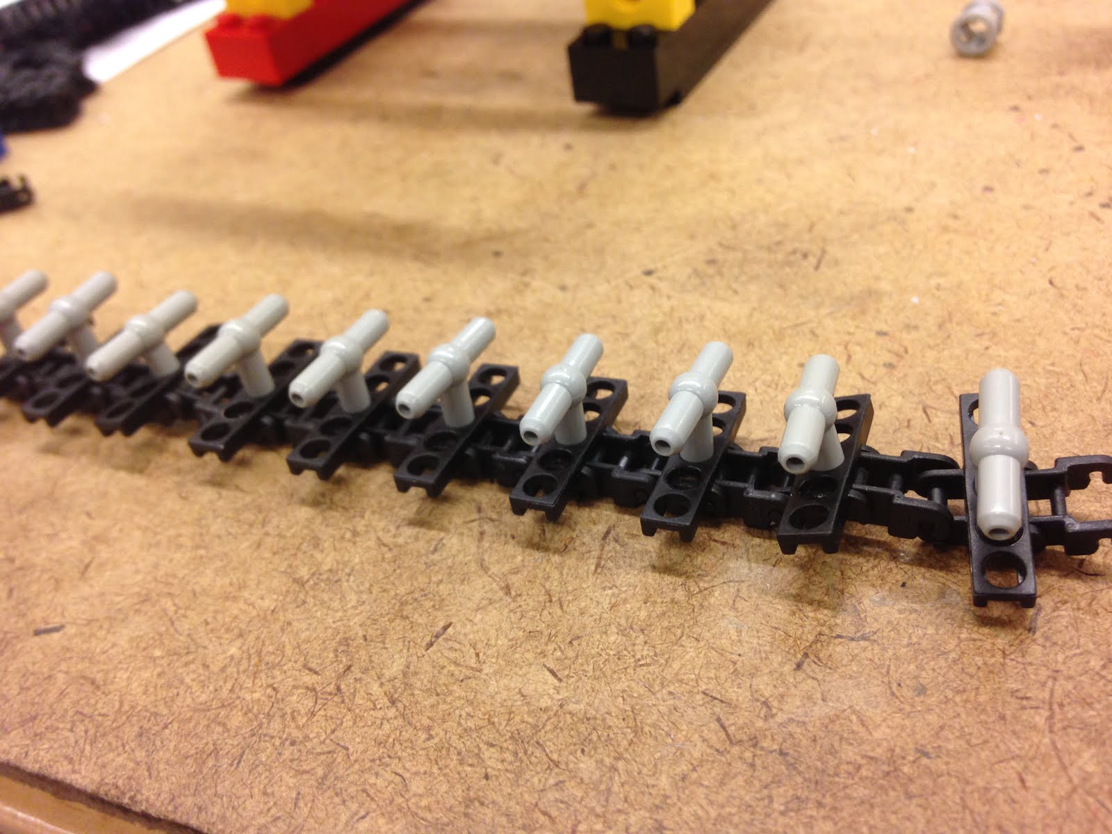
We made many iterations of the part surrounding the tracks but after hours of work, we ended up with these two that both worked well. The one on the left is stair like on the inside while the one on the right is more like a chimney.


With our tube finally here, we cut the 6 foot long tube into 12 6 inch long tubes. We first measured and marked the huge tube using a ruler and an erasable marker and then cut it using the power saw. Nearly all of the tubes were about the same height except for one which was clearly not as tall as the rest but we probably do not need all of 12 of the tubes so we're all good.

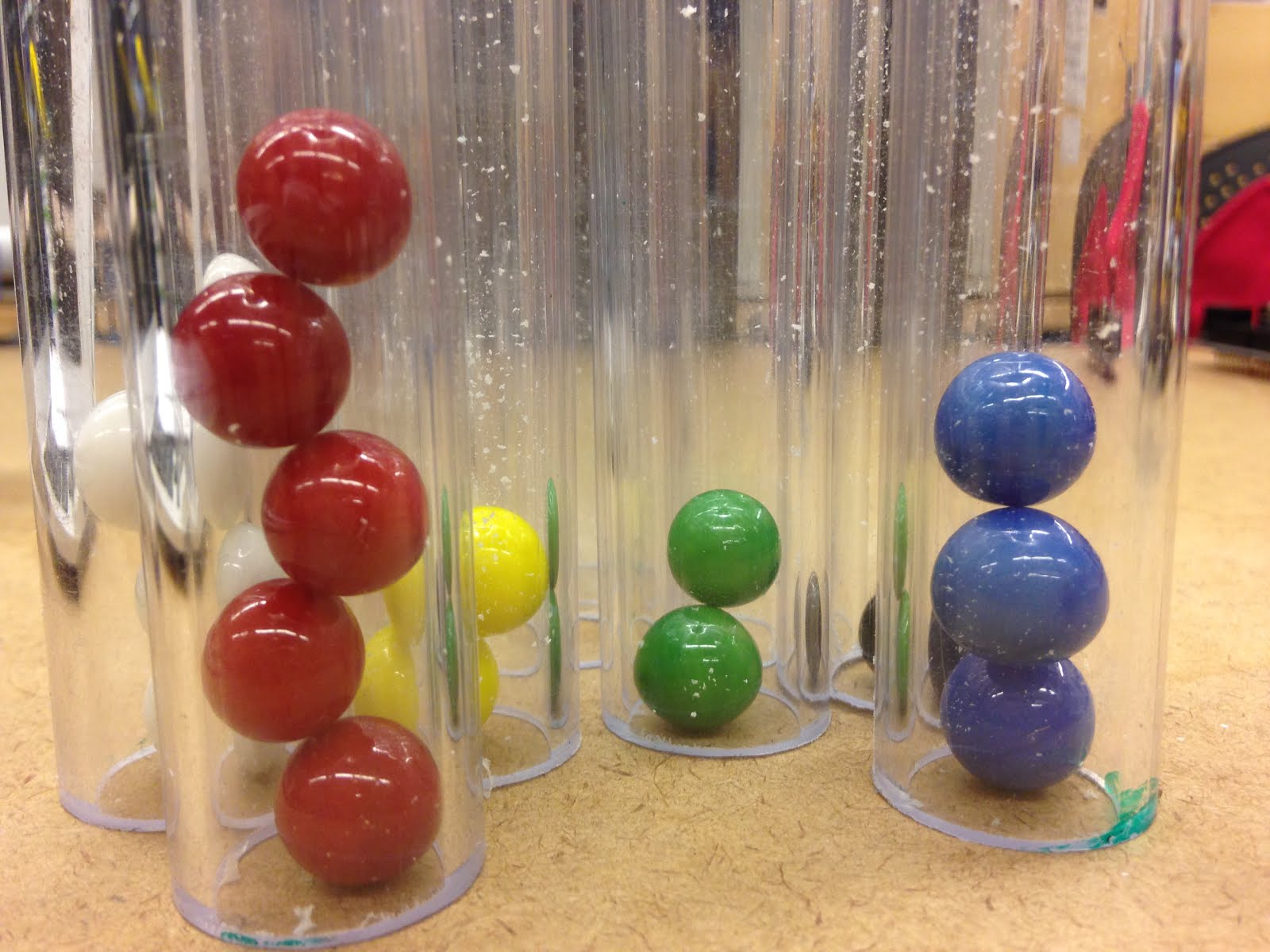
With the tubes and marbles finally here, we finally tested if the light sensor would be able to distinguish between an empty tube and a tube with marbles. With the more colored marbles, the light sensor worked great but it was a bit iffy with the yellow and white marbles. I found that the light sensor found a clear tube to have a value of 95, white marbles in the tube to be a value of 93/94, and yellow marbles to be around 91/92. The red, blue, green, and black marbles all came in at a much lower value. Since a clear tube had a light sensor value of 95, we said that if the light sensor value is greater than or equal to 95, turn on motor 1 but if it is less than 95 turn on motor 2 and motor 3.Once we installed the light sensor to the marble releasing mechanism though the values changed and we found that a value of 75 worked much better.


A major problem we encountered this week was us realizing that the bricktronics shield only had two ports for motors. So we had to try to figure out a way for one motor to move both the top and bottom tube holders. This really stumped us. First we thought of using a chain of gears climbing up but that idea was never executed since it just seemed to be too complicated. We then thought of building a contraption that would have the two top and bottom platforms to be connected to each other. We tried building this idea and it seemed like it would work but then we thought of using 3 servo motors. We tried coding the motors to move from position 0 to position 30 pause for 1 second and then move from position 31 to 60 and so forth until it reached position 180 and then it would go back to 0. This worked but not very well. It barely moved the tracks. We then thought about perhaps connecting a motor to a sensor port and writing in the code that motor 3 was in a sensor port. This did not work. We looked up if there were bricktronics that could hold more than 2 motor ports and we found that those were available. I thought that we would have one in the room so I went hunting for it and found it on the table in the back. But while we were asking Amy if we could use it, we also realized that we could connect the top and bottom tubes using a really long stick. After hours of thinking and building we finally found an answer!


We found that as the marbles were emptied from the tubes and into the marble releasing mechanism, 6 marbles would fall into the structure but they would be below the light sensor so the sensor could not sense that they were there and it would read that there was an empty tube, stop and the other motor that shifts the tubes would turn on. We fixed this by writing in the code that we would run the function releasemarble (makes the motor turn on for half second to turn the track and let one marble out) 6 times and then shift the tubes whenever the light sensor sensed that there were no marbles in front of it.

We then had to tackle the problem of how to attach the tubes to the tracks. We found velcro strips in the room and decided that we would hot glue them to the tracks and the tubes. This seemed like a fairly easy idea but we found out that this was totally not the case. We spent about 3 hours trying to successfully execute this idea and it's still in the works.


We first hot glued the the whole strip to the tracks but once we tried having the tracks run, it broke! We found that this was because the tracks became shorter as it curved on the gear. We thought that perhaps first gluing the tracks on flat on the table would work but it did not. We also tried gluing the velcro on the tracks but having a bit of extra velcro so that hopefully as the track curved on the gears there'd be enough velcro on the straight parts that it wouldn't break. This idea worked for one run and then broke. We then figured that gluing little sections of velcro would be the best. This worked the best out of all of our ideas but it still beaks so hopefully next week we can figure out how to fix this problem.

We also made a little funnel made out of paper cones so that the marbles being released could go straight into the tube down below it.

As we ran the tracks with the tubes connected to them we found that the tubes' bottom would get stuck on the raised parts of the lego so to fix this temporarily we placed paper on top of the lego platform.


Next week, we have to figure out a a different way to attach the tubes to the tracks. We're thinking of either just directly using the velcro strips as the track going around the gears but we'd have to create friction for it so that it would actually turn with the gears. We're also thinking of using headbands and sewing it to the tracks and then gluing the velcro strips on top of the headband.

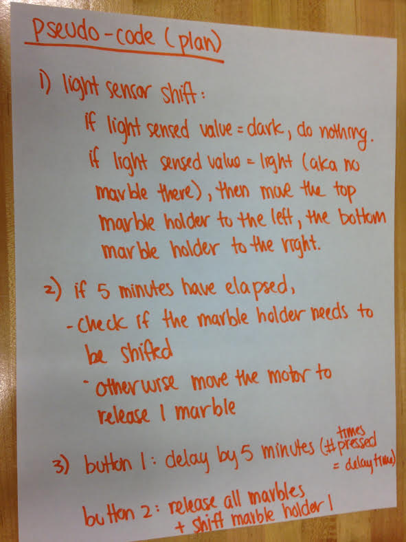
We also have to create the platform out of delrin so that it would be smooth and the tubes won't catch on it. Since the tubes are wobbly by themselves, we were thinking of moving the tracks higher so that the velcro could be higher and also maybe creating a structure that will work similarly to the paper in the video holding the tubes upright. We also have to add two buttons to the whole thing somewhere and write a code that says that if one of the buttons is pressed, there'd be a delay of 5 min and if the other button is pressed, it would fast forward 5 min.

Monday, April 18, 2016

Final Project Part II: Prototyping Week 1


Initial prototype


sketches of initial prototype

We started off week two with this prototype and with the idea of having a long tube hold the marbles from the top and then empty out into a clear container that will have dividers. The container at the bottom would rotate every time an activity ended. We initially planned to use a weight sensor to sense the weight of each marble and write a program that converts the number of marbles into the number of minutes an activity was but then we realized we could also use a color sensor to sense when a new activity was. The color sensor was more than $40 though which would nearly be our whole budget. With more thinking, we realized that we could probably just use a light sensor to sense when a marble was in the tube or not. This then led us to change our long tube on the top plan and instead have separate tubes for each activity.


So we thought of two ways the tubes on the top and bottom of the machine would be. One would be to have the two layers attached by beams so that when one moved, the other would be pulled along. We also thought of them going opposite directions and they'd be attached separately to a different motor.


We then had to figure out where we we wanted to place the light sensor. We couldn't place it on top of the tubes looking down since it would sense the machine underneath the tube.  We decided that having the sensor below the tube might work well. But the light sensor could not be right underneath the tube because of its shape so we thought of positioning it a little to the side and make steps for the marbles to roll down on to the light sensor and then the releasing mechanism.


We also thought of perhaps placing the light sensor horizontally to the side but still underneath the tubes so that it would sense when the tube has been empty of marbles, the tubes above would shift one over so that the next tube could be emptied. The tubes on the top would be standing on top of a platform so that the marbles would be held inside of the tubes but once the tubes shifted to the space above the marble releasing part, the marbles would be able to drop down on the releasing mechanism.


 And then Jennifer wrote out a plan of how our code will be.


So this week, we were finally able to finalize our material orders to the 6 foot long clear PVC pipe and a bag of marbles. We will also need three motors, an arduino, and bricktronics shield for the the mechanism that shifts the tubes. Next week, we plan on tailoring the marble releasing mechanism to the marbles we ordered, build the mechanism that shifts the tubes, and write up the code.


Friday, April 15, 2016

MATLAB: Thermal Systems Part II.

Deliverable 1:
Code of test.thermal.m
First run of test_thermal. We moved the container of the system for a second and it caused a sudden spike in the temperature which is the little blip on this graph. 

We learned from our mistake and made sure not to disturb the system which gave is this nice graph.

Thermal resistance (Rth) can be calculated using this equation:
Rth = Δ T / Power = y(300) - y(0) / power = (378.4592 -315.1095) / 6.5 =63.3497 / 6.5 = 9.7 K/W

Heat Capacity (C) can be calculated using this equation:
C = Power/ slope = power / [(y(50) - y(0))/50] = 6.5 / (22.87 / 50) = 14.2 J/K

To gut check the math, we can use this equation  \tau = Rth*C  = 9.7 K/W * 14.2 J/K = 137.4 s

Using the graph we determined that y(0) = 315.1095 and y(300) = 378.4592. The y value of (378.4592 - 315.1095) * 63.2% is 40. So the x value that corresponds to a change of temperature that is 40 degrees is the time constant. Using a ruler, we determined that a temperature of 40 degrees is around the x value of 130 seconds which is close to the calculated 137.4 s.

So although we predicted that the system would heat up 63.2% in 137.4 s, it actually took about 130 s. The percent error is 5.39% which is pretty low so the experiment is pretty close to the simulation.
:D This percent error is much lower than the usual 20% or so percent error I get in my chem labs so nice nice I am satisfied with this.

Deliverable 2:
Code for heat simulation
Heating simulation curve

The simulated heat curve is very similar to the experimental curve that we got from earlier. It's nearly exactly the same! :)

Deliverable 3: Bang-bang control

 
Simulation of bang bang control
Experimental results of bang bang control 
For bang bang control, we used a simple if/else statement for the experiment. We said that if the temperature was less than 340 then turn the power to 100% but if it is more than 340 then turn off the power. The experimental results were fairly similar to the simulation. The experimental just fluctuated a little bit more than the simulation but it is a given that that will happen since there is a delay between the time the sensor senses the temperature and when the power is adjusted.
Code for bang bang control of simulation.
Code for experimental heating using bang bang control. 
Deliverable 4:
Code for heat simulation using proportional control.
Code for heat experiment using proportional control.

Simulation using 0.02 gain. 
Experimental results using a 0.02 gain


kp = 0.02 | With a very small gain of 0.02, the system never reaches its control set point since the power is too small and does not cause a large enough temperature change for the system to reach its target.

*note: We accidentally used a gain of 0.02 instead of 0.05 but both gains are so small that I would expect that a gain of 0.05 would behave very similarly to these runs. 


Simulation using a 0.2 gain.
Experimental results using a 0.2 gain.

Simulation using 0.5 gain
Experimental results using 0.5 gain.


kp = 0.2 | The optimal gain seemed to be 0.2 since the simulation and the experimental both behaved similarly to the first runs we performed of heatsim.m and test_thermal.m.


kp=0.5 | When the system has a high proportional gain like 0.5, the system behaves similarly to the system that we used bang-bang control on. From the beginning of the experiment until, the system reaches it's target temperature, it increases linearly. When the system reaches the target temperature, it levels out like seen in these graphs.

Monday, April 11, 2016

Final Project Part I: Brainstorming and Planning

For our final project, Jennifer and I will be working with the Child Study Center to fix some problems that the CSC has and improve the experience of the children and the teachers. Out of the numerous problems and possible ideas that Becky from the CSC provided, Jennifer and I decided to either focus on the problem of controlling noise levels in the classroom or creating a device that would show the children how much time had passed and how much time is still left in an activity or day.

For the problem of controlling noise levels, we though of the idea of creating a dial that would have 3 levels of sound sensitivity that the teacher could control. The teacher could set it for very sensitive (used perhaps during nap time), moderately sensitive (group time), and not very sensitive (play time). The device would sense the sound level of the room and if it was within a good range for the current sensitivity, the mechanical arm or light would remain on green then if it got louder for a few minutes it would move to the yellow region. If room becomes quiet again, the arm or light would go back to green or if it got louder it would move to red.

For the problem of teaching time to young children, we came up with the idea of creating basically a timer/clock and using marbles to show time. Marbles would be held in some sort of a container on the left side and when a certain activity begins, a certain number of marbles that correspond with the amount of time of the activity would roll down a ramp and onto a sensor that would sense the marbles' weight. This weight would then be converted to time. After the amount of time that the activity was has passed, marbles corresponding to the length of the next activity would roll down and the cycle starts again. Every activity would have its on color marble.

Jennifer and I decided to work on the marble clock since Amy said that it was more interesting and the dial device we thought of for controlling noise levels would not work as well as a stoplight. Since the stoplight did not have a mechanism and our marble timer had a mechanism, we chose the marbles.

So for our device, we would have to create the marble releasing mechanism, a ramp, and a container for the marbles.
sketch of our marble time device

While browsing through different marble releasing videos on YouTube we got inspiration from this video that had a simple releasing mechanism made out of Legos. For our device, marbles would be funneled down through a tube and then at the very bottom there'll be a block that would move left and then right to release and push one marble out.

sketch of our marble releasing mechanism
But when we started building our prototype using the Legos, We found that a track with notches could instead be used to regulate the release of the marbles.
sketch of sensor side of device
While making the prototype and new marble release mechanism, we found that a ramp between the marble releasing part and the sensing and collecting part would no longer be necessary.

When we presented our idea to Becky she was concerned about a few things.

One was where this device would be. We said that it would be hung high up on a wall so children could see it but not touch it. It would also have some sort of screen over it so that no kid could possibly get a marble and choke on it.

Another concern was what if a teacher wanted to cut an activity short or if an activity needed more time. We came up with placing two buttons on the device; one that when pressed would delay the moving on to the next activity and another that would stop the time for the current activity and move right on to the next one.

Another concern was the sorting of marbles and setting up the device for the next day. We came up with the idea oh having a container that had separations in it. Marbles for one activity would go to one section and when it was time for the next activity's marbles to be released, the container would be rotated so that the new marbles would be placed into a new section. Then at the end of the day, The marbles can be placed back into the tube in the order of activities for the next day.
1st prototype


Tuesday, April 5, 2016

MATLAB: Thermal Systems

Q1: How does the cooling behavior change if we vary the parameters Rth and C?
C is the heat capacity of a liquid which is the amount of energy the can be applied before a temperature change occurs. So when C is increased, it takes a much longer time for the coffee cool down while when C is decreased, the coffee is able to cool down very quickly. Rth is the thermal resistance of  a substance. So when Rth is increased, the coffee cools down very slowly while when Rth is decreased, it cools down nearly instantly.
C = 1000 | Rth = 0.85

C = 5000 | Rth = 0.85
C = 100 | Rth = 0.85
C = 1000 | Rth = 10
C = 1000 | Rth = 0.01

Q2: Calculate a good value for P if we want our coffee to heat up to the Starbucks ideal of 84 degrees Celsius, using the Rth frm the MATLAB script.

(P/C) = (dT/dt) + ((T-Tair)/(Rth*C))
Because dT = 0 and dt = 0 initially we can simplify the equation to:
(P/C) = ((T-Tair)/(Rth*C))
The C on both sides cancel out and we are left with:
P = (T-Tair) / Rth
P = (357-293) / 0.85 = 64 / 0.85 = 75


Working Backwards: Can you dedeuce the thermal parameters C and Rth?
In order to find Rth, we use the equation:
P = (T-Tair) / Rth
Rth = delta T / P = 63 K / 75 W = 0.84 K/W

In order to find C, we can use the equation:
dT/dt = P/C
because at t=0, there is only energy flowing into the system.
SO we can rearrange the equation and get:
C = P / slope = (75 W) / (0.075 K/s) = 1000 J/K

Q3: Heat coffee using bang bang control
Bang bang control is appropriate for thermal systems because it is much simpler to just turn on and off a heater. It can be insufficient though because even with just a slight deviation from a target temperature a heater would immediately turn on or off causing a waste in energy.


Q4: Heat coffee using proportional control
With proportional control, we heat the coffee according to the amount it needed to go back to the ideal temperature and so the power did not always have to be at its maximum. The heat put into the system is proportional to the amount the temperature of the coffee deviated from the ideal 84 degrees.


Q5: Delay
Adding in a delay in bang bang control did not change the system very much. When the delay was larger than 10 though, we could see when the temperature would fluctuate from below ideal to ideal temperature.


delay 10 seconds
delay 25 seconds


Adding a delay in proportional control causes a huge difference in the very beginning. We can see that a large amount of heat was first added in the beginning since there was a large difference in the temperature of the coffee and the ideal temperature. Then as the temperature of the coffee got closer to the ideal, the heat added was more constant.